
行业资讯
粉料撒布车怎么制作过程技术
来源:https://www.sddhfjx.com/ 日期:2022-12-02
一种具有出料可控功能的水泥撒布车,,包括车体1,所述车体1的顶部外壁放置有料仓10,料仓10的一侧外壁通过螺栓固定有控制模块6,控制模块6内部设有速度传感器和显示屏,速度传感器的型号为djs-11,速度传感器通过can总线连接车体1的车辆控制系统,料仓10的一侧外壁通过螺栓固定有报警器14,报警器14的开关控制端与控制模块6电性连接,在控制模块6内提前输入需要撒布物料的体积密度或者质量密度参数,工作过程中,速度传感器对车体1的行驶速度进行实时检测,并传递信号给控制模块6,当车速高于或低于设定值时,控制模块6电性连接控制报警器14发出警报,对人们进行预警,控制模块6进行数据分析并传输数据给显示屏,便于人们实时查看。
A cement spreader with controllable discharging function, comprising a vehicle body 1, wherein a bin 10 is placed on the top outer wall of the vehicle body 1, a control module 6 is fixed on one side of the outer wall of the bin 10 through bolts, a speed sensor and a display screen are set inside the control module 6, the model number of the speed sensor is djs-11, the speed sensor is connected to the vehicle control system of the vehicle body 1 through the can bus, and an alarm 14 is fixed on one side of the outer wall of the bin 10 through bolts, The switch control end of the alarm 14 is electrically connected with the control module 6. The volume density or mass density parameters of the materials to be spread are input in advance in the control module 6. During the working process, the speed sensor detects the running speed of the vehicle body 1 in real time and transmits the signal to the control module 6. When the vehicle speed is higher or lower than the set value, the control module 6 electrically connects the control alarm 14 to give an alarm to warn people, The control module 6 analyzes the data and transmits the data to the display screen for real-time viewing.
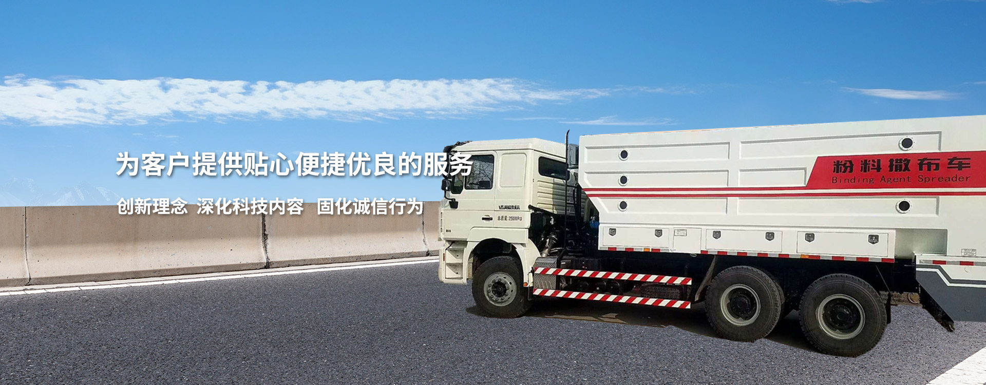
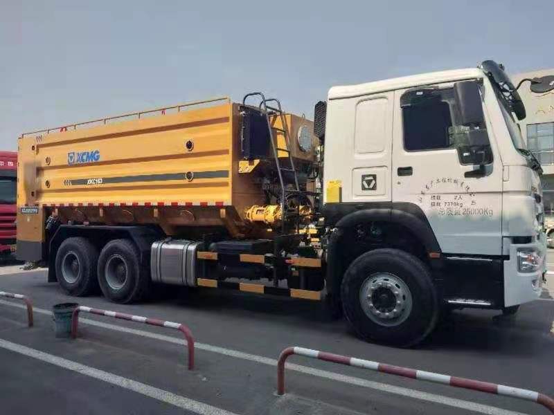
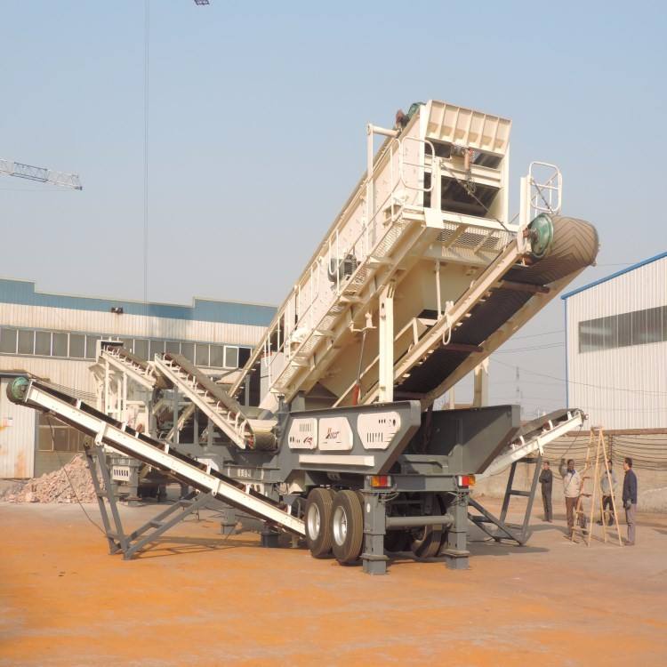
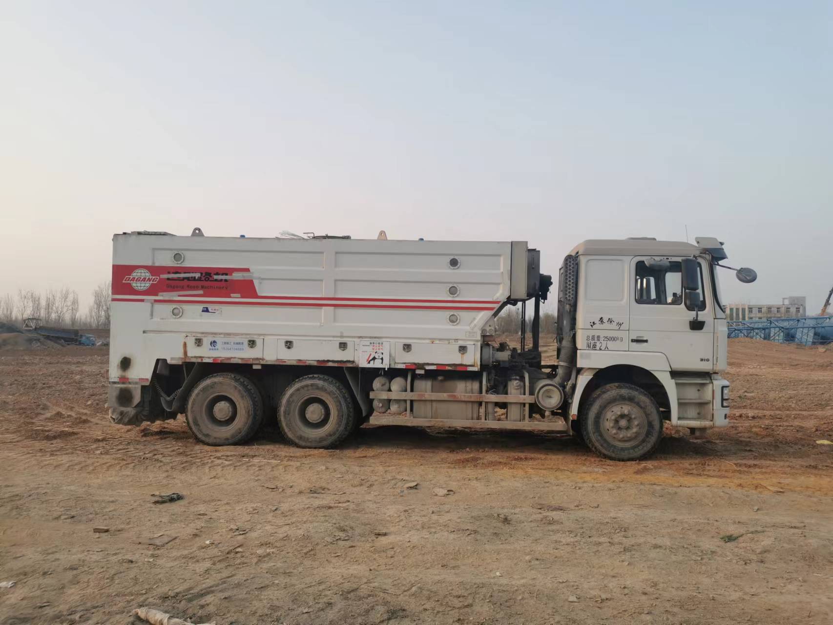
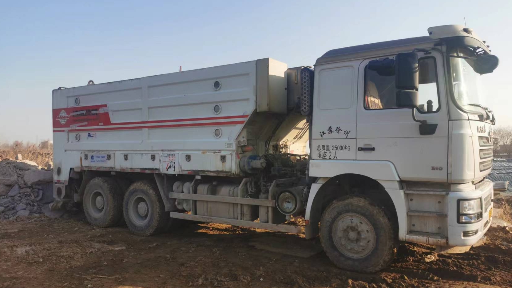
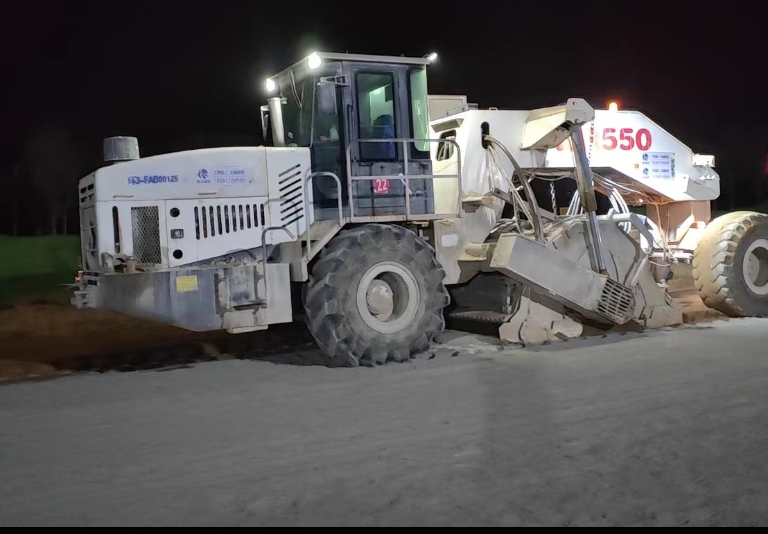
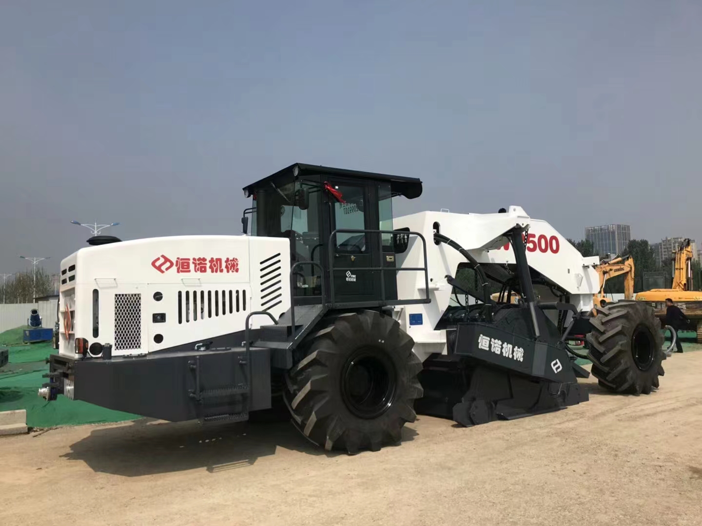
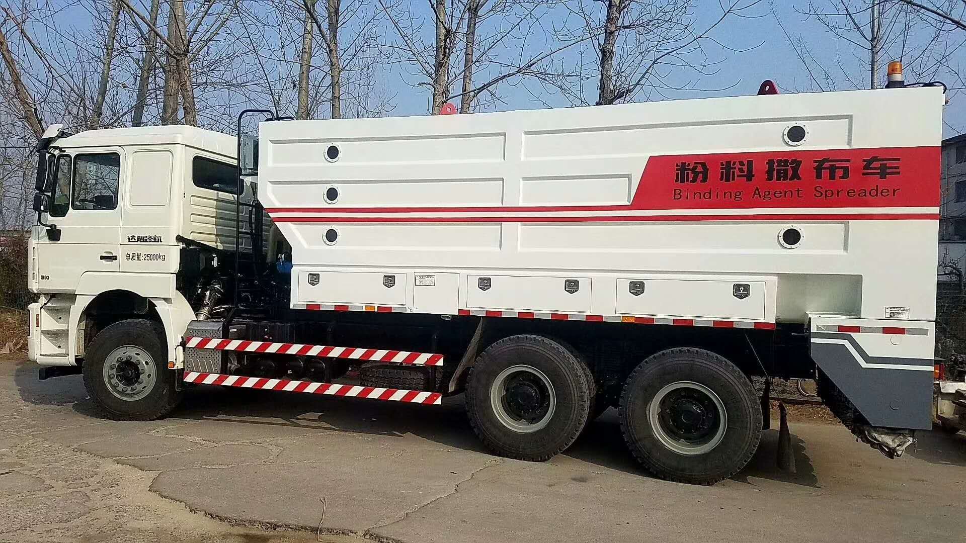
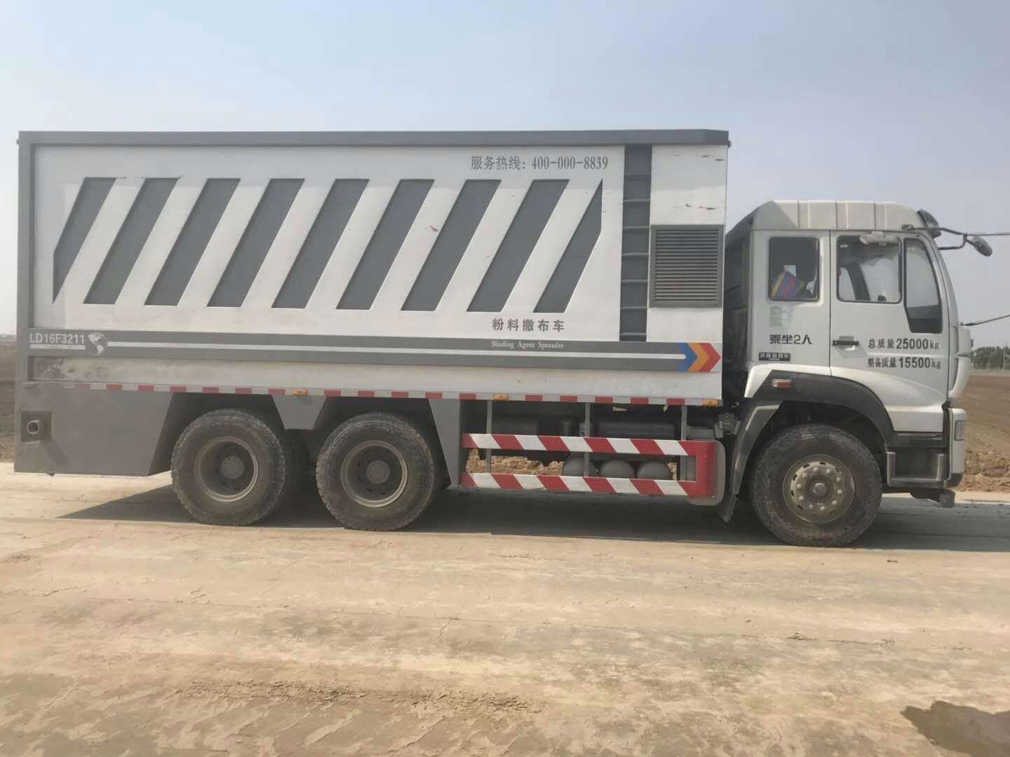
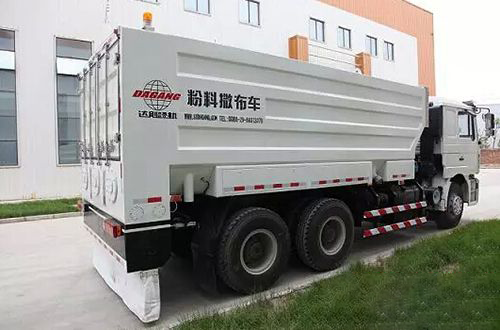
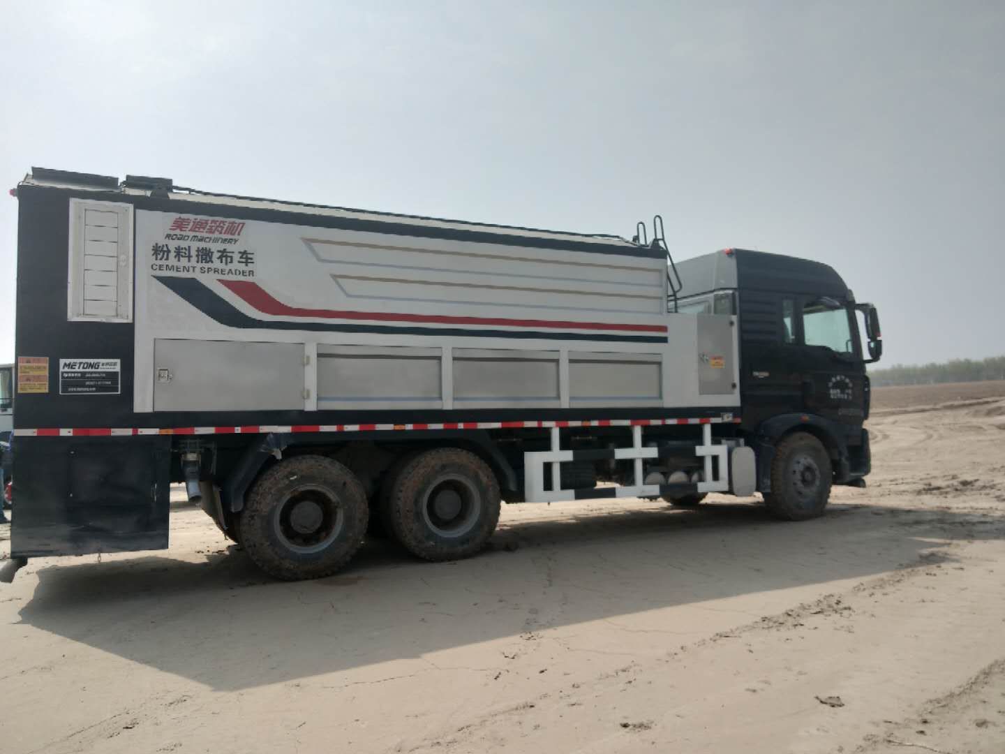
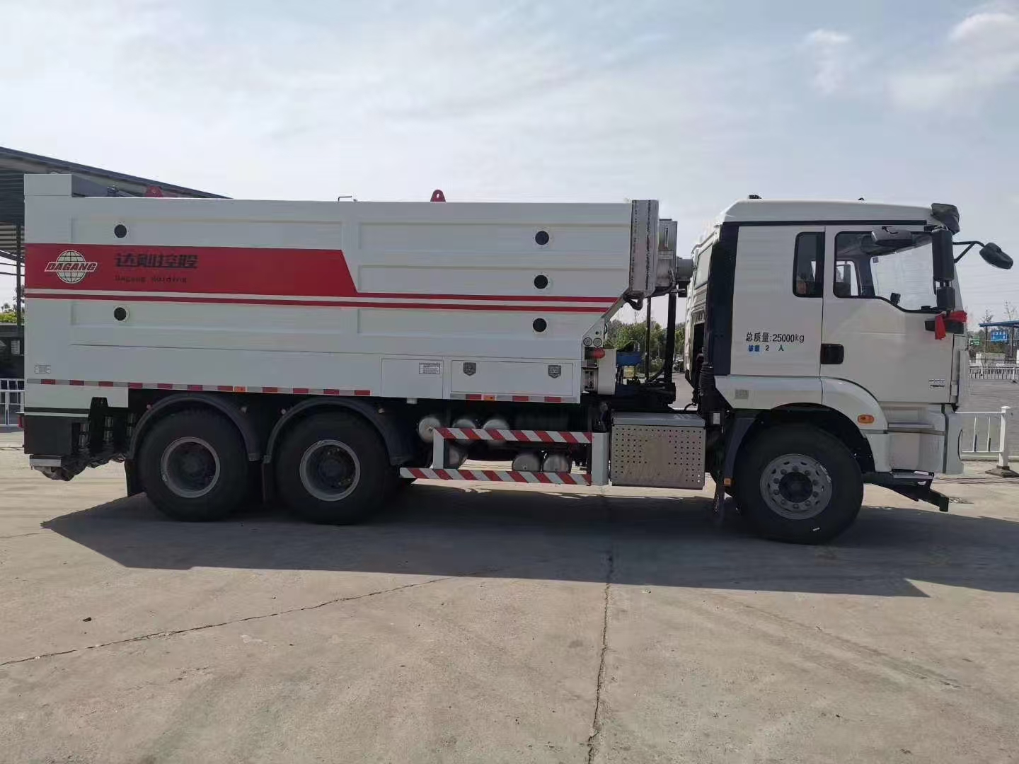
粉料撒布车
Powder spreader
为了对需铺设的路面进行碾压;,所述车体1的底部外壁通过螺栓固定有固定座2,固定座2的两侧内壁通过转轴转动连接两个滚筒4,车体1的一侧外壁通过螺栓固定有出料箱8,料仓10的底部外壁通过螺栓固定有一电动伸缩板9,一电动伸缩板9的开关控制端与控制模块6电性连接,车辆行驶过程中,两个滚筒4随着车辆前进在固定座2内转动,对需铺设的路面进行碾压,控制模块6电性连接控制一电动伸缩板9的开关,使得物料通过出料箱8进行出料,便于撒布作业。
To roll the pavement to be paved;, The outer wall at the bottom of the car body 1 is fixed with a fixing seat 2 through bolts, the inner walls at both sides of the fixing seat 2 are connected with two rollers 4 through rotating shafts, the outer wall at one side of the car body 1 is fixed with a discharge box 8 through bolts, the outer wall at the bottom of the silo 10 is fixed with an electric expansion plate 9 through bolts, the switch control end of an electric expansion plate 9 is electrically connected with the control module 6, and the two rollers 4 rotate in the fixing seat 2 with the vehicle moving forward during the vehicle driving process, The road surface to be paved shall be rolled, and the control module 6 electrically connects and controls the switch of an electric expansion plate 9, so that the materials can be discharged through the discharge box 8, which is convenient for spreading.
为了避免加料过程中粉尘飞扬;,所述料仓10的顶部外壁通过螺栓固定有粉料箱13,粉料箱13的顶部外壁通过螺栓固定有固定板,固定板的一侧外壁通过螺栓固定有弹簧12,粉料箱13的两侧内壁通过螺栓固定有转动轴,转动轴的圆周外壁套接有挡板19,弹簧12的另一端通过螺栓与挡板19的顶部外壁相连接,向粉料箱13内添加粉料时,粉料下沉在挡板19上,弹簧12弹性变形拉伸,挡板19的一端受力下滑,挡板19通过转动轴使得粉料箱13打开一定角度进行加料,添加粉料完毕后,弹簧12收缩,使得挡板19一端向上回位,从而对粉料箱13进行闭合,避免加料过程中,粉尘飞扬引起大气污染。
To avoid flying dust during feeding;, The top outer wall of the bin 10 is fixed with a powder box 13 by bolts, the top outer wall of the powder box 13 is fixed with a fixing plate by bolts, one side of the outer wall of the fixing plate is fixed with a spring 12 by bolts, the inner walls on both sides of the powder box 13 are fixed with a rotating shaft by bolts, the outer wall of the circumference of the rotating shaft is sleeved with a baffle 19, and the other end of the spring 12 is connected with the top outer wall of the baffle 19 by bolts. When powder is added to the powder box 13, The powder sinks on the baffle 19, the spring 12 is elastically deformed and stretched, and one end of the baffle 19 slides under the force. The baffle 19 makes the powder bin 13 open at a certain angle for feeding through the rotation axis. After the powder is added, the spring 12 shrinks, making one end of the baffle 19 return upward, thus closing the powder bin 13, so as to avoid air pollution caused by flying dust during the feeding process.
为了便于控制粉料的输入量;所述粉料箱13的一侧外壁开设有安装槽,料仓10的顶部外壁通过螺栓固定有二电动伸缩板11,二电动伸缩板11的开关控制端与控制模块6电性连接,二电动伸缩板11的一端与安装槽相匹配,且二电动伸缩板11的顶部外壁通过螺栓固定有称重传感器18,称重传感器18的型号为pts124-133g,称重传感器18的信号输出端与控制模块6电性连接,向粉料箱13内添加粉料过程中,称重传感器18实时检测二电动伸缩板11上的重量变化,当达到设定值时,传递信号给控制模块6,控制模块6电性连接控制二电动伸缩板11开关,使得粉料箱13内的物料下滑至料仓10内,严格控制粉料的输入量,确保后期的水泥质量。
In order to control the input amount of powder; One side of the outer wall of the powder bin 13 is provided with an installation slot, the top outer wall of the bin 10 is fixed with two electric expansion plates 11 through bolts, the switch control end of the two electric expansion plates 11 is electrically connected with the control module 6, one end of the two electric expansion plates 11 is matched with the installation slot, and the top outer wall of the two electric expansion plates 11 is fixed with a weighing sensor 18 through bolts, and the model of the weighing sensor 18 is pts124-133g, The signal output end of the weighing sensor 18 is electrically connected with the control module 6. During the process of adding powder to the powder bin 13, the weighing sensor 18 detects the weight change on the two electric expansion plates 11 in real time. When the set value is reached, the signal is transmitted to the control module 6. The control module 6 is electrically connected to control the switch of the two electric expansion plates 11, so that the materials in the powder bin 13 slide into the bin 10, and the input amount of powder is strictly controlled, Ensure the cement quality in the later period.
为了便于向料仓10内添加水;所述料仓10的顶部外壁通过螺栓固定有水箱15,水箱15的圆周外壁通过螺栓固定有输水管,输水管的圆周外壁通过螺栓固定有电动阀门22,电动阀门22的开关控制端与控制模块6电性连接,料仓10的一侧外壁通过螺栓固定有透视窗5,透视窗5的一侧外壁粘接有刻度线,打开电动阀门22,水箱15通过输水管向料仓10内添加水,期间,通过透视窗5可以清晰了解水箱10内的物料使用情况。
To facilitate the addition of water to bin 10; The top outer wall of the silo 10 is fixed with the water tank 15 by bolts, the peripheral outer wall of the water tank 15 is fixed with a water delivery pipe by bolts, the peripheral outer wall of the water delivery pipe is fixed with an electric valve 22 by bolts, the switch control end of the electric valve 22 is electrically connected with the control module 6, one side of the outer wall of the silo 10 is fixed with a perspective window 5 by bolts, one side of the outer wall of the perspective window 5 is bonded with a scale line, and the electric valve 22 is opened, The water tank 15 adds water to the silo 10 through the water delivery pipe. During this period, the use of materials in the water tank 10 can be clearly understood through the perspective window 5.
为了控制水的输入量;所述料仓10分为上料仓10和下料仓10,上料仓10和下料仓10之间通过螺栓固定有隔板,上料仓10的一侧内壁通过螺栓固定有液位传感器23,液位传感器23的型号为lk1022,液位传感器23的信号输出端与控制模块6电性连接,水箱15通过输水管向上料仓10内添加水时,液位传感器23实时检测上料仓10内的液位变化,当水位达到设定值时,传递信号给控制模块6,控制模块6电性连接控制电动阀门22的开关,严格控制水的输入量,进一步确保水泥的质量。
To control the water input; The bin 10 is divided into an upper bin 10 and a lower bin 10. A partition is fixed between the upper bin 10 and the lower bin 10 through bolts. A liquid level sensor 23 is fixed on one side of the inner wall of the upper bin 10 through bolts. The model of the liquid level sensor 23 is lk1022. The signal output end of the liquid level sensor 23 is electrically connected with the control module 6. When the water tank 15 adds water to the upper bin 10 through the water pipe, the liquid level sensor 23 detects the change of the liquid level in the upper bin 10 in real time, When the water level reaches the set value, the signal is transmitted to the control module 6, which is electrically connected to control the opening and closing of the electric valve 22 to strictly control the water input to further ensure the quality of cement.
为了便于制备水泥,所述料仓10的一侧外壁通过螺栓固定有两个支撑座,两个支撑座的顶部外壁分别通过螺栓固定三电机16和四电机17,上料仓10的两侧内壁通过转轴转动连接有两个螺旋辊21,两个螺旋辊21的输入端通过联轴器分别与三电机16的输出端和四电机17的输出端相连接,分别启动三电机16和四电机17开关,带动两个螺旋辊21进行旋转作业,对上料仓10内的粉料与水进行搅拌作业,制备成水泥。
In order to facilitate the preparation of cement, two support seats are fixed on one side of the outer wall of the silo 10 through bolts, the top outer walls of the two support seats are respectively fixed with three motors 16 and four motors 17 through bolts, the inner walls on both sides of the feeding silo 10 are connected with two spiral rolls 21 through rotating shafts, and the input ends of the two spiral rolls 21 are respectively connected with the output ends of three motors 16 and four motors 17 through couplings, Start the three motor 16 and four motor 17 switches respectively to drive the two spiral rollers 21 to rotate, and mix the powder and water in the feeding silo 10 to prepare cement.
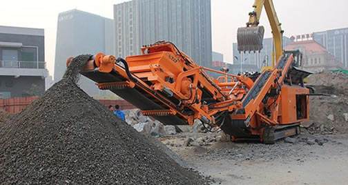
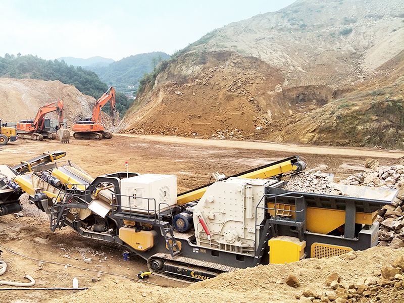
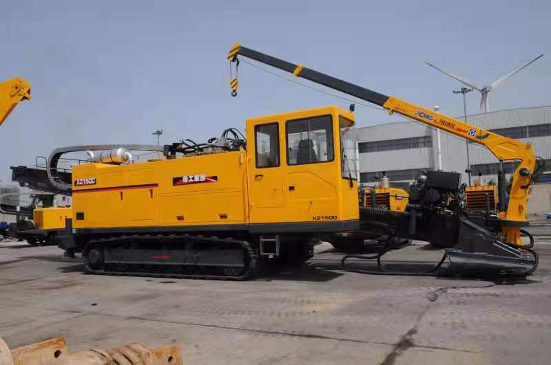
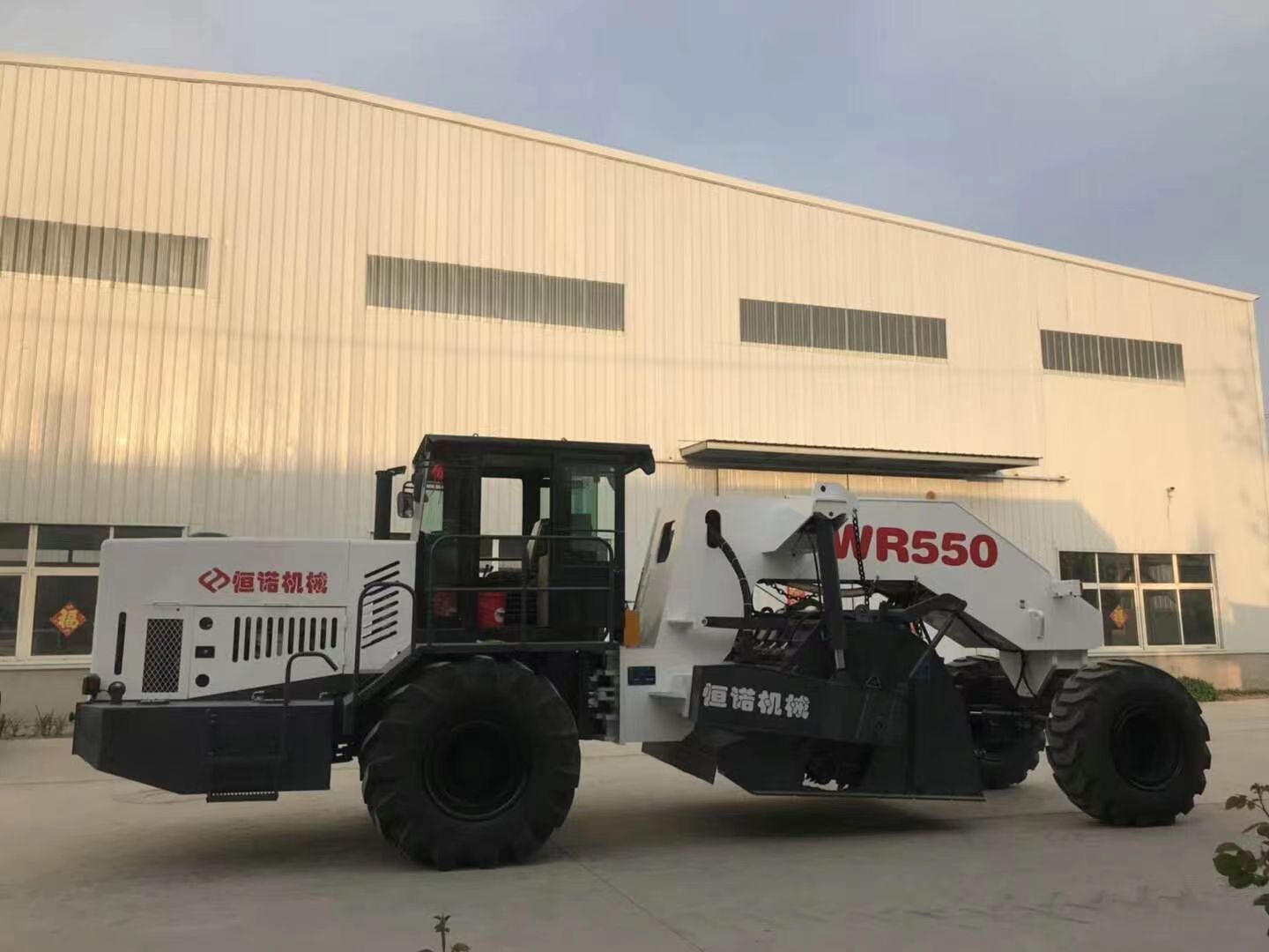
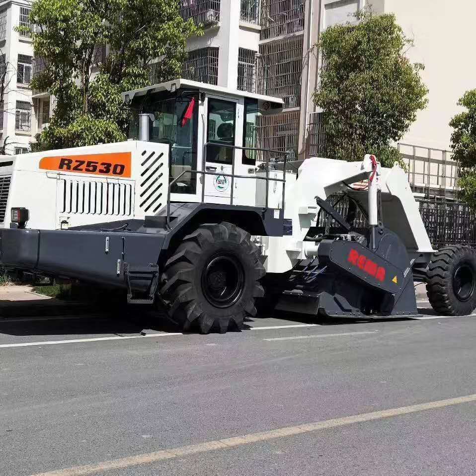
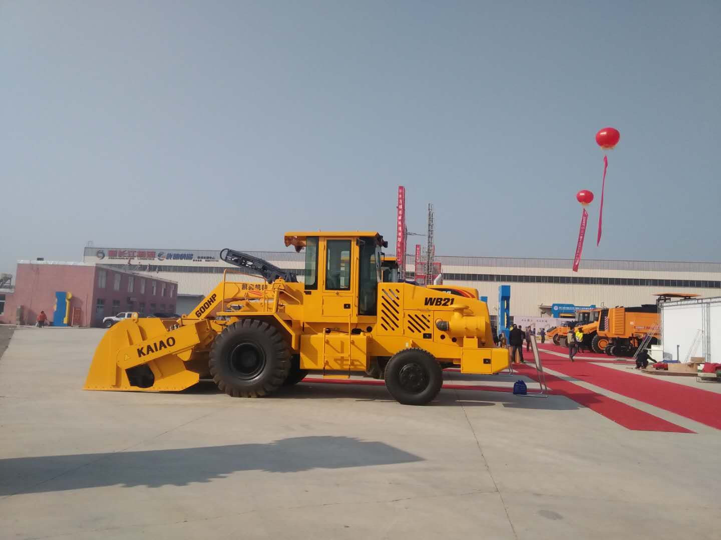
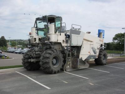
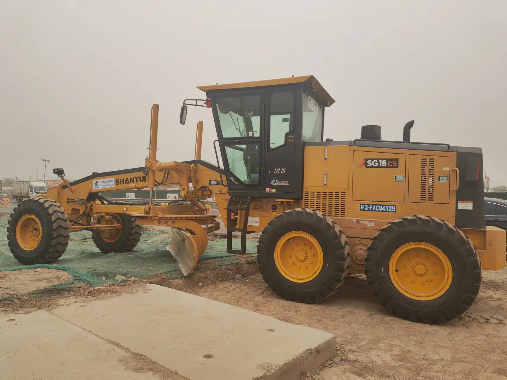
水泥洒布机出租
Rental of cement distributor
述隔板的顶部外壁开设有下料槽20,隔板的底部外壁通过螺栓固定有三电动伸缩板26,三电动伸缩板26的开关控制端与控制模块6电性连接,水泥制备完毕后,控制模块6电性连接控制三电动伸缩板26的开关,使得上料仓10的水泥随着螺旋辊21的旋转向下料槽20处输送,下落至下料仓10内部。
The top outer wall of the diaphragm is provided with a blanking tank 20, and the bottom outer wall of the diaphragm is fixed with three electric expansion plates 26 through bolts. The switch control end of the three electric expansion plates 26 is electrically connected with the control module 6. After the cement preparation is completed, the control module 6 electrically connects and controls the switch of the three electric expansion plates 26, so that the cement in the feeding bin 10 is transported to the feeding tank 20 along with the rotation of the spiral roller 21 and falls into the inner part of the unloading bin 10.
为了输送物料进行处料;所述下料仓10的两侧内壁均通过转轴转动连接有两个转动辊,两个转动辊的圆周外壁套接有同一个输送带25,输送带25的底部面与下料仓10的顶部面留有3cm的间隙,料仓10的一侧外壁通过螺栓固定有一支撑板,一支撑板的顶部外壁通过螺栓固定有一电机3,一电机3的开关控制端与控制模块6电性连接,且一电机3的输出端通过连接轴与其中一个转动辊的输入端相连接,控制模块6电性连接控制一电机3工作,带动转动辊进行旋转,从而使得输送带25进行输送物料作业。
Handling for conveying materials; The inner walls on both sides of the blanking bin 10 are rotationally connected with two rotating rollers through a rotating shaft. The outer walls of the circumference of the two rotating rollers are sleeved with the same conveyor belt 25. A gap of 3cm is left between the bottom surface of the conveyor belt 25 and the top surface of the blanking bin 10. One side of the outer wall of the bin 10 is fixed with a support plate through bolts. The top outer wall of a support plate is fixed with a motor 3 through bolts. The switch control end of the motor 3 is electrically connected with the control module 6, The output end of a motor 3 is connected with the input end of one of the rotating rollers through a connecting shaft. The control module 6 electrically controls the operation of a motor 3 to drive the rotating rollers to rotate, so that the conveyor belt 25 can transport materials.
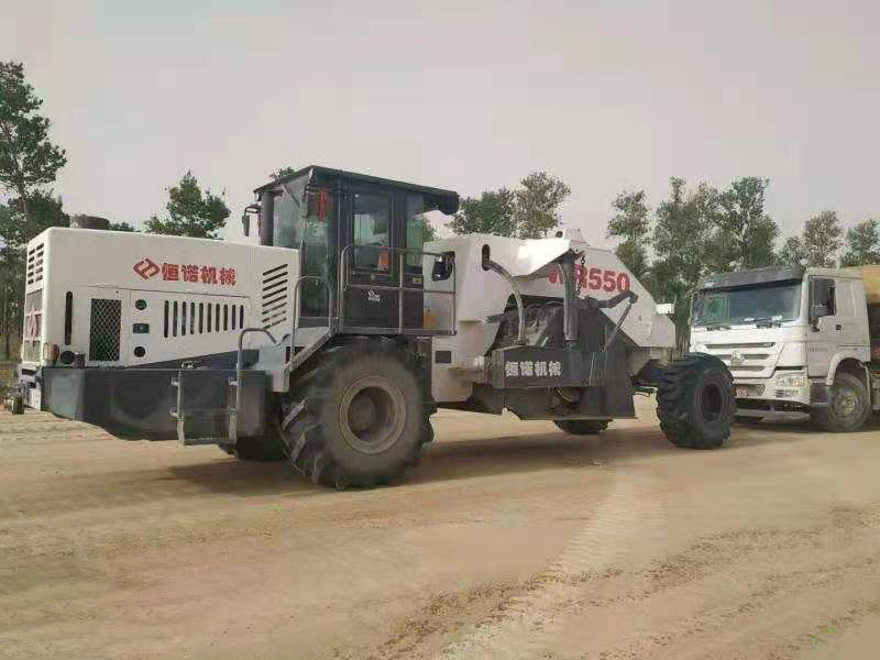
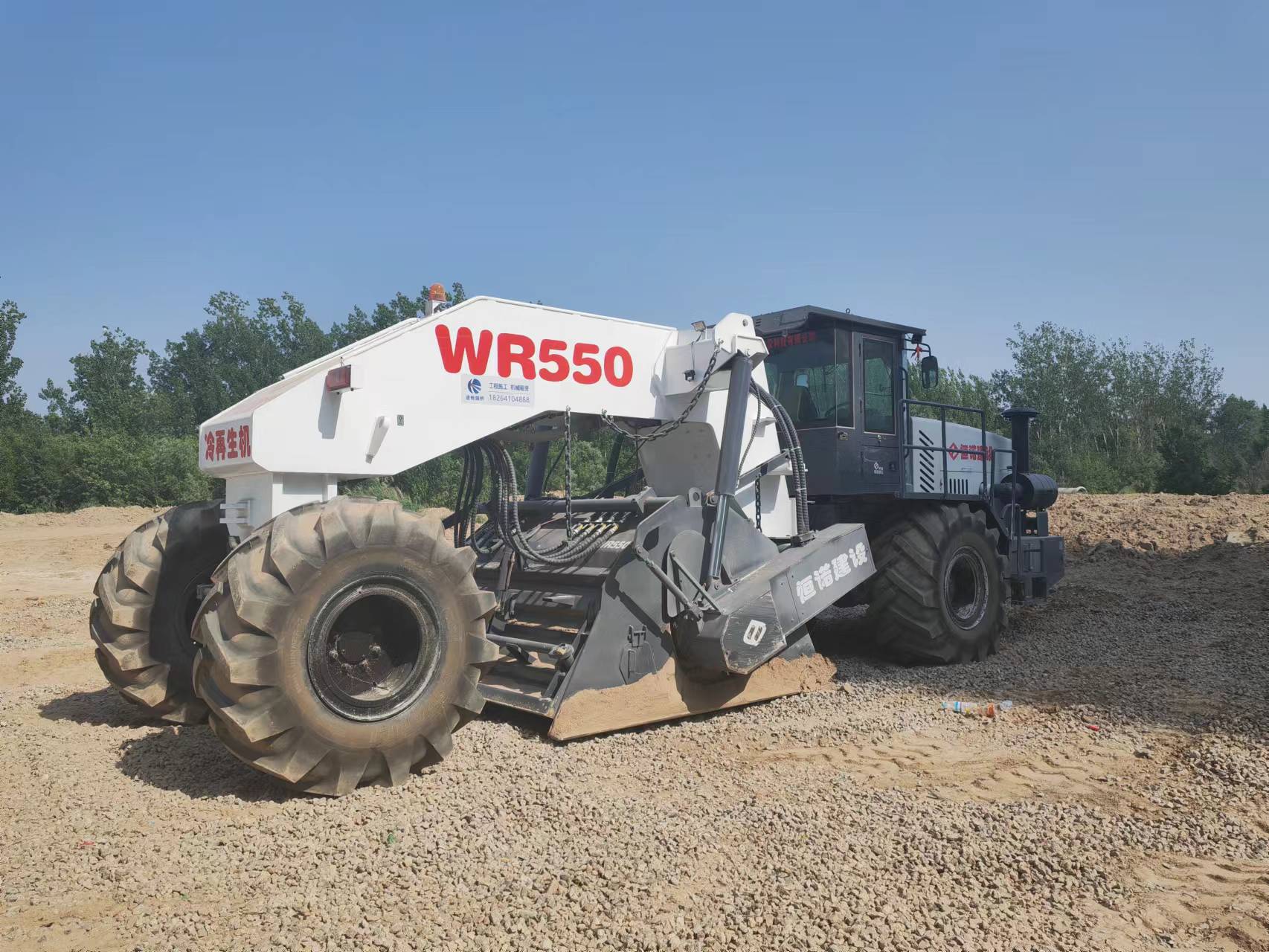
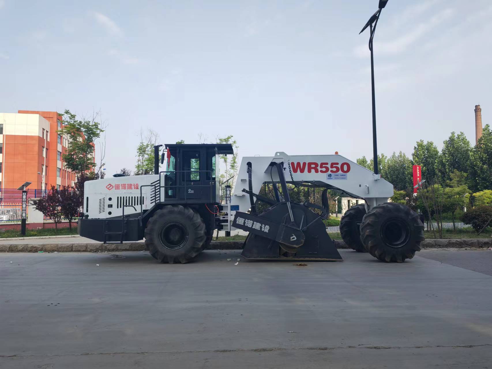
以上就是为大家介绍的有关冷再生机租赁的详细的介绍,希望对您有所帮助.如果您有什么疑问的话,欢迎联系我们.我们将以的态度,为您提供服务https://www.sddhfjx.com
The above is a detailed introduction to the rental of the cold regenerator. I hope it will be helpful to you. If you have any questions, please contact us. We will provide services for you with our attitude https://www.sddhfjx.com


 公司地址:济南市槐荫区经一路273号群盛华城2号楼1-404
 公司名称:山东途畅路桥工程有限公司
  备案号:
备案号: